Piston-Crank Mechanism Part-1
Summary
In this tutorial we will create a piston-crank mechanism as shown below. Piston-crank mechanisms are used to convert linear motion into angular (rotational) motion or vice versa. In automotive engines linear motion of the pistons is converted to rotational motion to rotate the tires. In this example we will do the opposite and convert rotational motion into linear motion.
In Part-1 we will create a circle to represent the crank while getting familiar with the Mekanimo workspace.
In Part-2 we will create a motor, piston, and a rod to finish the model.
Figure 1: Final model.
Setting up the work place
Start Mekanimo. Your screen should look similar to the picture below. If your screen resolution is too low you may want to increase it so that the canvas area is big enough to work comfortably.
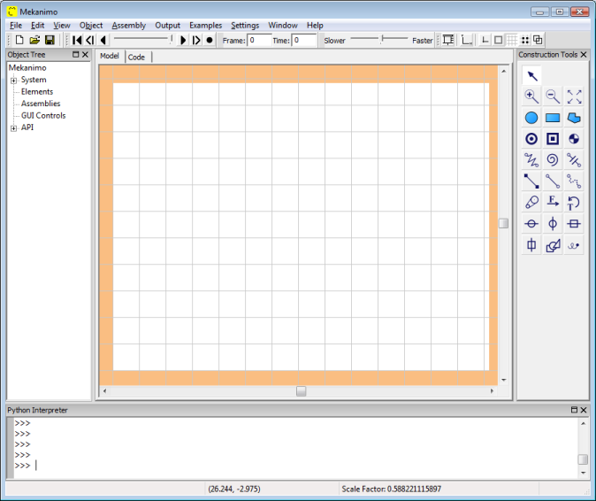
Figure-2: Mekanimo main window.
Deactivate the box
In many simulations we may need an enclosed area to prevent objects from flying into space. Since this is a frequently used setting Mekanimo provides a default box that can be resized, activated, and deactivated. Since we will have no free falling objects in this model we will get rid of the box by clicking on the box toggle button (shown below with a red arrow).
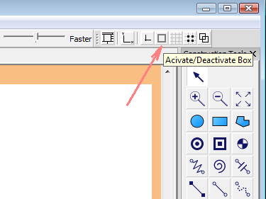
Figure-3: System box
Set the grid
To precisely align the objects while creating them with the mouse a grid can be a great time saver. Mekanimo can display a grid on the canvas and mouse clicks can be directed to the grid points if the snap to grid option is on. To turn the grid on click on the Show/Hide Grid button, do the same thing for snap to grid. Both buttons are shown with red arrows below.
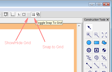
Figure-4: Grid
Set the canvas mode to CIRCLE
Now we are going to create a circle to simulate the crank. When you hover the cursor on the circle tool (red arrow) a short help text (toolbar tip) is displayed. All other tools have similar short explanations displayed when the cursor is hovered upon them. Click on the circle tool. Now the circle tool should be toggled on as shown on the right. This sets the canvas mode from SELECT to CIRCLE.
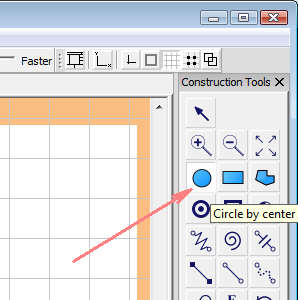
Figure-5: Circle mode
Create a circle by center and radius
Now left-click on the canvas (somewhere around the center of the circle in the picture below) and drag the mouse (keep the left mouse button down while dragging) and release the left mouse button when the radius of the circle is similar to the circle in the picture below.
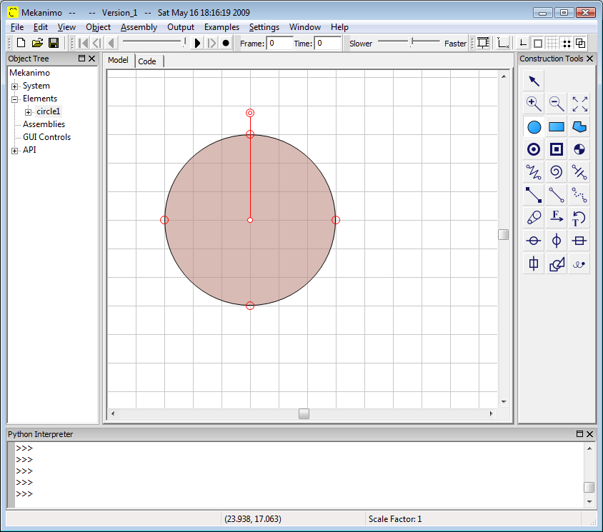
Figure-6: Circle
Observe the Object Tree.
When an element is created, several actions are automatically performed by Mekanimo. Now let’s go through some of these actions.
The circle you created is added to the Object Tree as shown below. A name (in this case ‘circle1’) is automatically assigned to the circle.
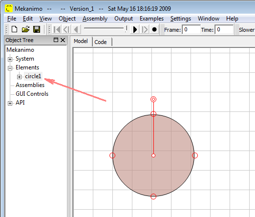
Figure-7: Object tree
Display the circle’s details in the object tree.
If you click on the plus sign right next to circle1 details of circle1 will be displayed in the object tree as shown below. If you hover the cursor upon any of the items that do not fit into the object tree’s frame, a tool tip text will be displayed to show the whole text of the item.
Alternatively, object tree can be resized by dragging its right edge. Circle’s position, area, weight etc. is automatically calculated and shown upon creation.
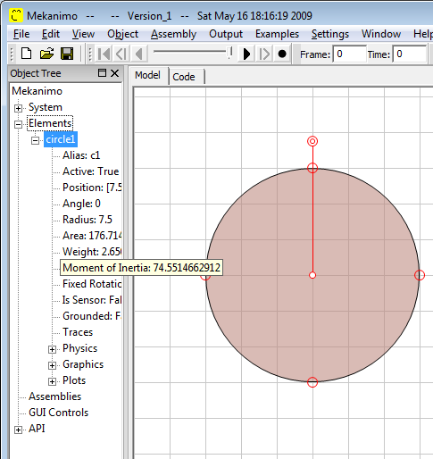
Figure-8: Object tree details
Handles and selecting/unselecting an object.
When an object is created, it is automatically selected. Selected elements are displayed with their rotation handle and resize handles as shown below. To select an object click on it when the canvas is in SELECT mode. To unselect an object click on an empty spot in the canvas (make sure the canvas is in SELECT mode). Multiple objects can be selected by dragging a selection rectangle or clicking on objects while holding the Shift key. Alternatively, objects can be selected by clicking on their names in the object tree.

Figure-9: Rotation and resizing handles
Go to the code editor.
Now click on the code tab shown below to go to the code editor.
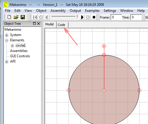
Figure-10: Code tab
Auto-code.
This will display the code editor as shown below (your dimensions and fillColor may look different). You can switch between the canvas and the code editor any time you wish. Mekanimo automatically generates Python code for almost all actions you take from the GUI.
If there are any modifications to the automatically generated code (auto-code) Mekanimo reflects these changes in the model when you go back to the canvas.
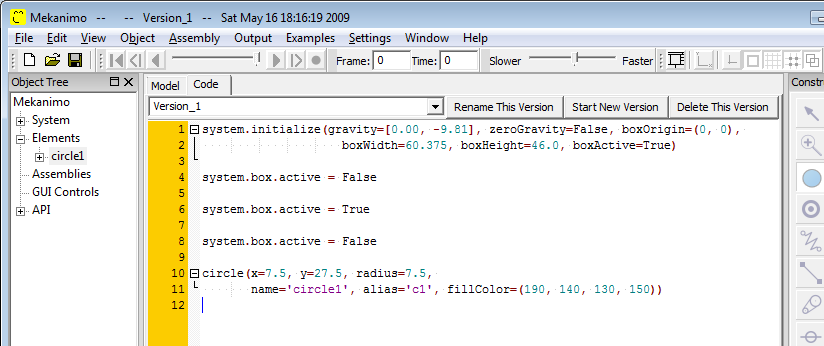
Figure-11: Automatically generated code
Rename circle1 as crank.
Mekanimo let’s users rename an object in several different ways. We can modify the code, we can click on the name item in object tree to highlihgt it and then reclick on the same item to type the new name, or go to the Python editor and type the line of code shown below to assign a new name to circle1. Go ahead and click on the name item in the object tree and rename the circle1 as crank.
>>> circle1.name = 'crank'
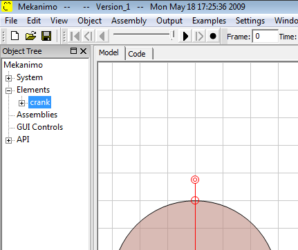
Figure-12: Rename
Save your work.
To save our progress so far, go to File -> Save As sub-menu and save this file in a directory you like as tutorial1.mek.
Run the simulation. Although we are far from a complete piston crank mechanism, we have a model that can be run. If you click on the run button you should see that our crank object falls down. Click on the pause button (see Fig. 14) to stop the simulation. Reset the model by clicking on the reset button shown below and then activate the box before rerunning the simulation.
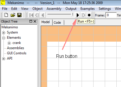
Figure-13: Run button
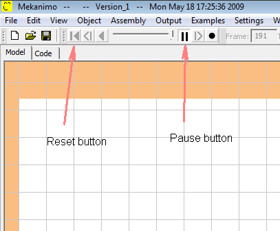
Figure-14: Reset and pause buttons
![]()
Table Of Contents
- Piston-Crank Mechanism Part-1
- Summary
- Setting up the work place
- Deactivate the box
- Set the grid
- Set the canvas mode to CIRCLE
- Create a circle by center and radius
- Observe the Object Tree.
- Display the circle’s details in the object tree.
- Handles and selecting/unselecting an object.
- Go to the code editor.
- Auto-code.
- Rename circle1 as crank.
- Save your work.