Piston-Crank Mechanism Part-2
Summary
In Part-2 of this tutorial we will create a motor to rotate the crank, a rectangle to represent the piston and a link to represent the rod (the piece that connects piston and crank) and run the simulation.
Set the canvas mode to MOTOR
To be able to create a motor to rotate the crank click on the motor tool shown below. This sets the canvas mode to MOTOR.
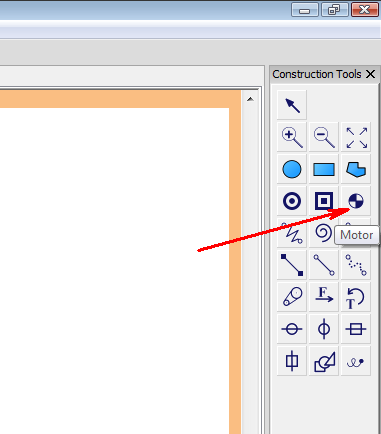
Figure-1: Motor tool.
Create a motor
Click on the center of the crank. This creates a motor as shown below and adds it to the object tree. You may want to go to the code editor and see the auto-code for creating a motor.
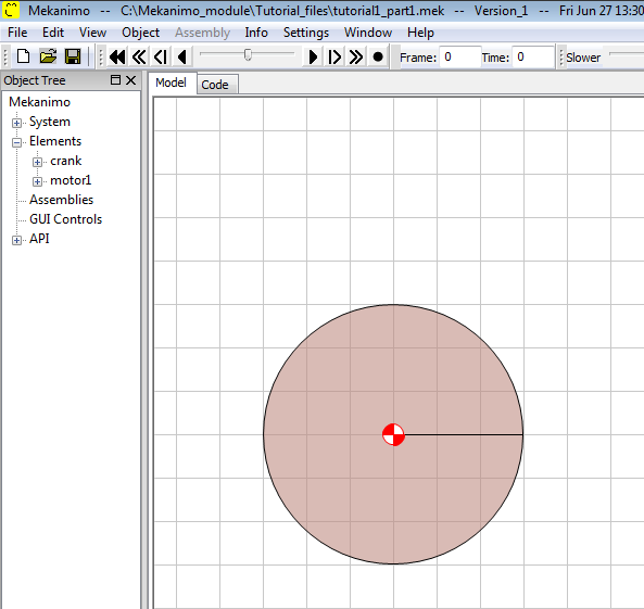
Figure-2: Motor located at the center.
Create the piston
We will create a rectangle to simulate the piston. Set the canvas mode to RECTANGLE by pressing on the ‘R’ key on the keyboard. This should set the canvas mode to RECTANGLE. If it doesn’t, click on an empty area in the canvas and then press the ‘R’ key. Then, click and drag to draw a rectangle similar to the one shown below. Rename rectangle1 as ‘piston’.
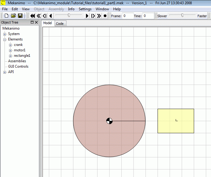
Figure-4: Piston.
Create the rod
To simulate a weightless rod to connect our piston and crank we will create a link object. Set the canvas mode to LINK by pressing on the ‘L’ key on the keyboard (You can click on the link button if you wish.). Then, click and drag to draw a link connector similar to the one shown below. Rename link1 as ‘rod’.
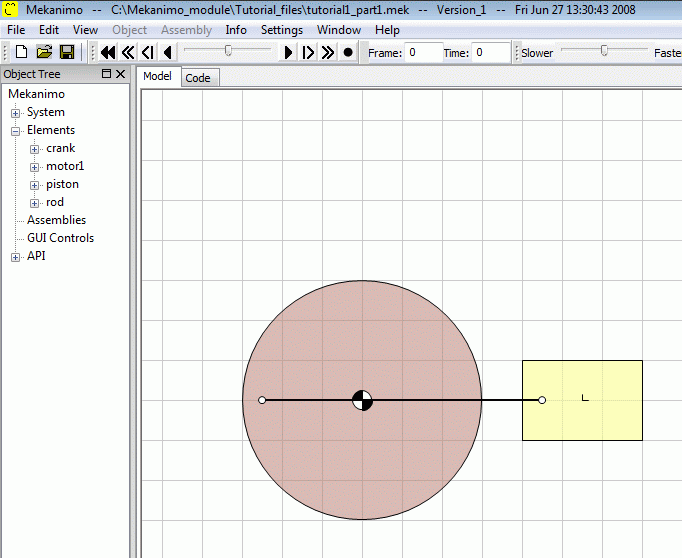
Figure-5: Rod.
Constrain the piston’s motion
In a physical model we would need a cylinder or a similar mechanism to make sure that piston can only move linearly. Although we can create two rectangles on top and bottom of the piston to guide it, it is easier to constrain the motion of the piston. Mekanimo provides horizontal and vertical constraints called horizontal rail (hRail) and vertical rail (vRail) to simulate situations like this. First set the canvas mode to HRAIL and click on the piston. Your model should look similar to the picture below.
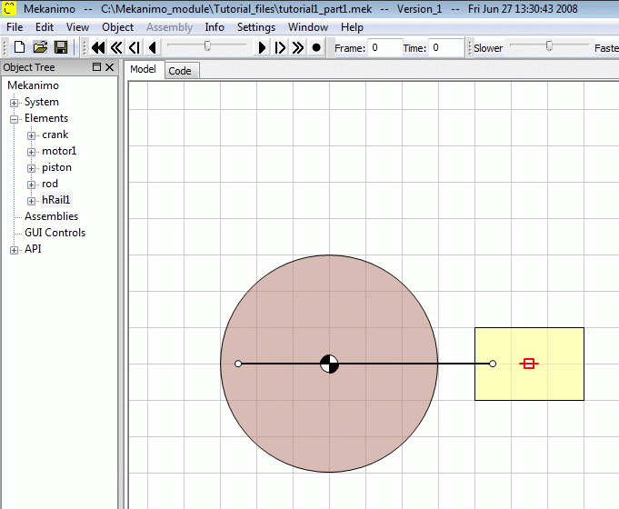
Figure-6: Horizontal constraint.
Run the simulation
Congratulations. You have modeled a piston-crank mechanism. Now you can run it.
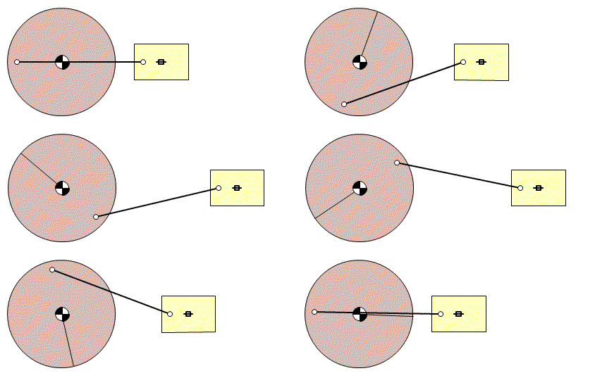
Figure-7: Final design.
