Connectors
Connectors are primarily used for connecting two rigid bodies together or connecting a rigid body to the ground. Connection points are defined in connected body’s local coordinates.
Connector reaction forces and reaction torque
Box2D reports the reaction force and torque for each connector. This could be useful for definining behaviors by using the connector forces or torque.
>>> pin2.box2DConnector.GetReactionForce(system.iterationsPerStep / system.dt)
b2Vec2(0,-14.7859)
Connector break force
If break force is defined on a connector, when the forces acting on the connector in question exceed the specified amount, the connector breaks (removed from the system). This is useful for simulating physical structures.
Beams
Beam connectors are used for connecting two rigid bodies to each other so that they behave like a single rigid body. Beam connectors behave same as weld connectors.
beam(body1=circle1, body2=rectangle1, b1x=9, b1y=0, b2x=-1, b2y=-1)
Chains
Chain connectors are used for preventing the distance between the two connection points becoming greater than the prescribed distance.
chain(body1=polygon1, body2=circle2, b1x=0, b1y=0, b2x=0, b2y=0)
Gaps
Gap connectors are used to prevent the distance between the two connection points becoming less than the prescribed distance.
gap(body1=polygon1, body2=rectangle1, b1x=10, b1y=0, b2x=-4, b2y=0)
Links
Link connectors are used to connect two rigid bodies to each other so that the distance between the connection points stays constant. Rigid bodies can rotate about the conneciton points.
link(body1=polygon1, body2=rectangle1, b1x=10, b1y=0, b2x=-4, b2y=0)
Motors
Motors are used for rotating a rigid body relative to another rigid body or the ground with constant angular velocity.
motor(body1=polygon1, body2=rectangle1, b1x=10, b1y=0, b2x=-4, b2y=0,)
Pins
Pin connectors (aka revolute joints) are used for constraining relative rotational motion of the connected bodies about a common point. Location of the pin connector is defined in terms of the local coordinates of the connected bodies.
pin(body1, body2, b1x, b1y, b2x=None, b2y=None)
Note
If the b2x and b2y is not provided then they are automatically computed.
Rails
Rail connectors (aka prismatic joints) are used for constraining the translations along a defined axis while constraining the rotational motion. Location of the rail connectors do not make any difference only their axis definition prescibe the allowed translation direction. Axes are defined by specifying a point. To visualize the axis this point should be connected to the origin. For example, an axis defined as [1, 1] forms a 45 degree angle with the positive x axis. For convenience the tool box contains two types of rails with pre-defined axis definitions as listed below.
Vertical Rails
Vertical rails’ axis definition is [0, 1]. Once this connector is applied to a rigid body, that rigid body can move along y axis only with no rotations.
vRail(body1=rectangle1, body2=ground, b1x=2.27301525047, b1y=-1.01022900021, name='vRail1', alias='vr1')
Axis definition can be modified by using the object tree or with code in the code panel or Python interpreter as shown below.
vRail1.axis = [1, 1]
Axis definition can be modified by using the object tree or with code in the code panel or Python interpreter. Double-clicking on the Axis node (see Figure 1) would bring up a dialog box with editable x and y directions.
Horizontal Rails
Horizontal rails’ axis definition is [1, 0]. Once this connector is applied to a rigid body, that rigid body can move along x axis only with no rotations.
hRail(body1=rectangle1, body2=ground, b1x=2.27301525047, b1y=-1.01022900021, name='hRail1', alias='hr1')
Axis definition can be modified by using the object tree or with code in the code panel or Python interpreter as shown below. Double-clicking on the Axis node (see Figure 1) would bring up a dialog box with editable x and y directions.
hRail1.axis = [1, 1]
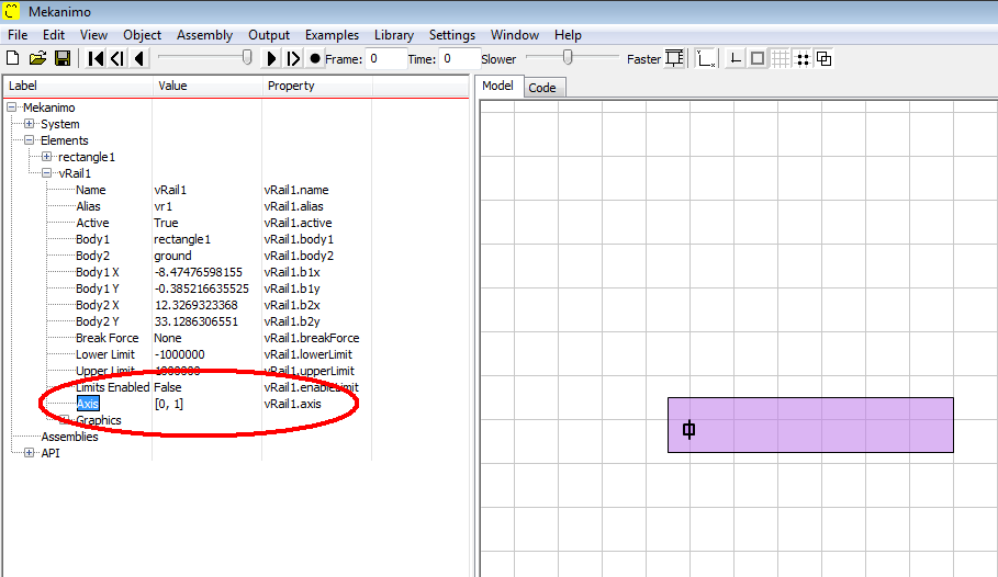
Figure 1: Rail axis node in the object tree.
Sliders
Slider connectors are used for constraining the translations along a defined axis without constraining the rotational motion. Unlike rail connectors, location of the slider connectors is significant. When a rigid body’s motion is constrained with a slider, the rigid body in question can move along an axis parallel to the defined axis direction and going through the defined point. Axes are defined by specifying a point. To visualize the axis this point should be connected to the origin. For example, an axis defined as [1, 1] forms a 45 degree angle with the positive x axis. For convenience the tool box contains two types of sliders with pre-defined axis definitions as listed below.
Vertical Sliders
Vertical sliders’ axis definition is [0, 1]. Once this connector is applied to a rigid body, that rigid body can move along an axis parallel to the y axis and going through the specified point.
vSlider(body1=rectangle1, body2=ground, b1x=2.27301525047, b1y=-1.01022900021, name='vSlider1', alias='vs1')
Axis definition can be modified by using the object tree or with code in the code panel or Python interpreter as shown below.
vSlider1.axis = [1, 1]
Axis definition can be modified by using the object tree or with code in the code panel or Python interpreter. Double-clicking on the Axis node (see Figure 2) would bring up a dialog box with editable x and y directions.
Horizontal Sliders
Horizontal sliders’ axis definition is [1, 0]. Once this connector is applied to a rigid body, that rigid body can move along an axis parallel to the x axis and going through the specified point.
hSlider(body1=rectangle1, body2=ground, b1x=-9.09656559121, b1y=7.1054273576e-15,
    name='hSlider1', alias='hs1')
Axis definition can be modified by using the object tree or with code in the code panel or Python interpreter. Double-clicking on the Axis node (see Figure 2) would bring up a dialog box with editable x and y directions.
hSlider1.axis = [1, 1]
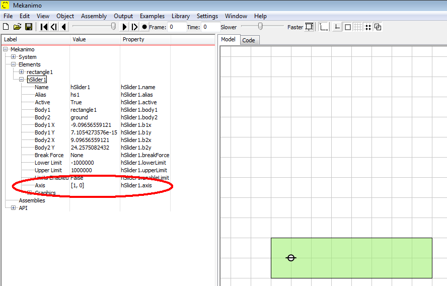
Figure 2: Slider axis node in the object tree.
Springs
Spring connectors are used for exerting forces to the connection points along the axis formed by two connection points. They can work under compression or tension.
spring(body1=polygon1, body2=rectangle1, b1x=10, b1y=0, b2x=-4, b2y=0)
Torsional Springs
Torsional spring connectors are used for exerting torque to the connected bodies.
torSpring(body1=polygon1, body2=rectangle1, b1x=10, b1y=0, b2x=-4, b2y=0)