Construction Tools
Construction tools (see Figure 4) are used to set the canvas mode. The user actions yield different results depending on the current canvas mode.
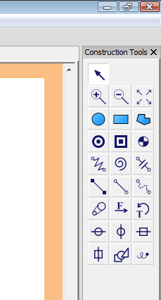
Figure 2: Construction tools
Select
Clicking on the selection tool (see Figure 3) sets the canvas mode to SELECT. While in SELECT mode you can select or modify existing items in the canvas.
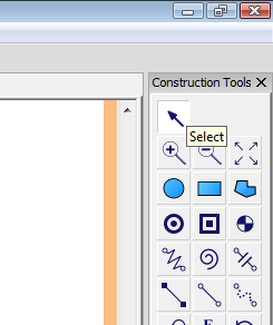
Figure 3: Selection tool
Tip
Middle mouse button click sets the canvas mode to SELECT.
You can click on an item to select it. Once selected the item is drawn with its selection handles if they exist. Selected items are also highlighted at the Object Tree. To select multiple items you can drag and draw a selection rectangle. Alternatively, you can hold the Shift key down while clicking on items to select multiple elements one by one.
Tip
Single or multiple items can be selected from the Object Tree too.
Zoom-in
Zoom-in tool (see Figure 4) is used for enlarging the objects in the canvas by changing the scale factor. If you click on a spot in the canvas, the clicked spot becomes the new center point and objects in the canvas are scaled up by a factor of canvas.zoomFactor (default value is 1.25). You can set the canvas.zoomFactor from the interpreter as shown below.
>>> canvas.zoomFactor = 1.1
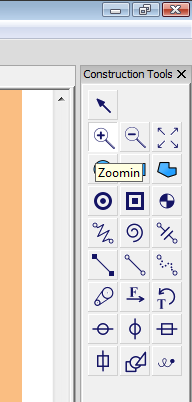
Figure 4: Zoom-in tool
If you draw a rectangle by clicking and dragging the mouse while in the zoom-in mode, the selection rectangle forms the new limits of the canvas. Double-clicking in the canvas while in the zoom-in mode sets the canvas scale factor to 1.
Note
Current canvas scale factor is displayed in the status bar.
Zoom-out
Zoom-out tool (see Figure 5) is used for shrinking the objects in the canvas by changing the scale factor. If you click on a spot in the canvas, the clicked spot becomes the new center point and objects in the canvas are scaled down by a factor of 1/canvas.zoomFactor (default canvas.zoomFactor value is 1.25, 1/1.25 = .8). You can set the canvas.zoomFactor from the interpreter as shown below.
>>> canvas.zoomFactor = 1.1
Note
Current canvas scale factor is displayed in the status bar.
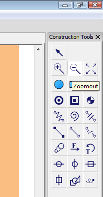
Figure 5: Zoom-out tool
Fit to screen
When you click on the fit to screen tool (see Figure 6), the new canvas scale factor is set so that all elements in the system fits in the canvas.
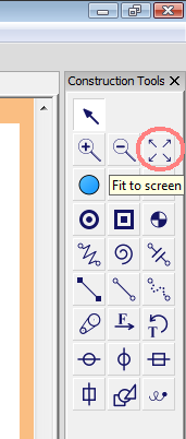
Figure 6: Fit to screen tool
Circle
Circle tool (see Figure 7) sets the canvas mode to CIRCLE. When you click and drag the mouse, clicked point becomes the center of the circle and the distance between the center and the current mouse position becomes the radius. When you let the left mouse button go a new circle is added to the system. Properties of this new circle can be edited from the object tree.
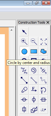
Figure 7: Circle tool
After creating the circle you can modify its properties by using the object tree, the code editor, or the Python interpreter. See rigid bodies for more information about modifying rigid bodies.
Rectangle
Rectangle tool (see Figure 8) sets the canvas mode to RECTANGLE. When you click and drag the mouse, clicked point becomes the starting corner of the rectangle and the distance between the center and the current mouse position becomes the diagonal of the rectangle. When you let the left mouse button go a new rectangle is added to the system. Properties of this new rectangle can be edited from the object tree.
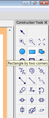
Figure 8: Rectangle tool
Polygon
Polygon tool (see Figure 9) sets the canvas mode to POLYGON. When you click on the canvas, clicked point becomes a vertex and moving the mouse and clicking again creates another vertex and forms the edge between these two vertices. To finalize the polygon you can either click on the first vertex or hit the Enter key.
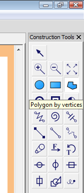
Figure 9: Polygon tool
Pin
Pin tool (see Figure 10) sets the canvas mode to PIN. When you click on a rigid body, if there is another rigid body overlapping the clicked point, a pin connector is placed at the clicked point to connect the two overlapping rigid bodies. If there are more than two overlapping rigid bodies at the clicked point then only the top two bodies are connected. If there are no overlapping bodies then the clicked body is connected to the ground at the clicked position.
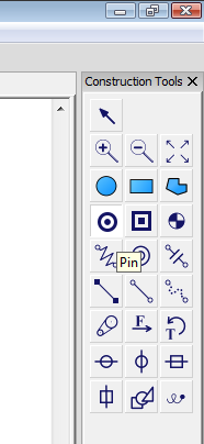
Figure 10: Pin tool
Weld
Weld tool (see Figure 11) sets the canvas mode to WELD. When you click on a rigid body, if there is another rigid body overlapping the clicked point, a weld connector is placed at the clicked point to weld (anchor) the two overlapping rigid bodies. If there are more than two overlapping rigid bodies at the clicked point then only the top two bodies are welded together. If there are no overlapping bodies then the clicked body is welded to the ground at the clicked position.
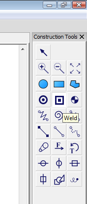
Figure 11: Weld tool
Motor
Motor tool (see Figure 12) sets the canvas mode to MOTOR. When you click on a rigid body, if there is another rigid body overlapping the clicked point, a motor connector is placed at the clicked point to connect the two overlapping rigid bodies. If there are more than two overlapping rigid bodies at the clicked point then only the top two bodies are connected together. If there are no overlapping bodies then the clicked body is connected to the ground at the clicked position. Motor connector, in essence, is a pin connector that applies constant torque to the connected bodies.
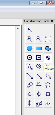
Figure 12: Motor tool
Spring
Spring tool (see Figure 13) sets the canvas mode to SPRING. When you click on a rigid body, the first attachment point of the spring is formed and when you clicked on another rigid body or the ground then the second attachment point is formed and spring is finalized.
Figure 11: Weld tool